Post

Visualizzazione dei post da dicembre, 2021

An odissey with some low cost noise generators

Immagine
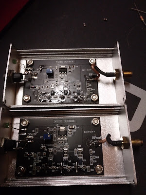
 Recently I have bought five  noise generators rated from 0.2 to 2000 MHz . After a quick check I have realized that no one of them worked correctly or at all , all of them with common problems of designing and/or building , and other with also additional problems ( loss of components , bad soldering , cables broken during constructions .... I supposed no one was really tested . This was a start of the odissey .....  Checking the basic circuits is is made by a noise diode polarized with an LM317 with variable voltage with a trimmer , a 3 dB attenuator , a cascade of three monolitic amplifiers and another 3 dB attenuator . The first hardware generated noise , while the second didn't because the output cable was cut in the middle after having rolling it while screwing the SMA till the cable broke into two pieces !  What you see is the module after repair ( you can note that the cable is shorter because I used the cut part remaining connected to the SMA connector ) .  In the first mod

HOW TO USE AN RTL KEY , HDSDR , VB HIFI CABLE AND SDR SPY FOR A FULL RDS FM DECODER

Immagine
Having already installed the software HDSDR for the RTL Key , you can add VB Cable and SDR SPY to build a full RDS FM Decoder . This are the link where you can download all what is needed :  1) HDSDR :  https://www.hdsdr.de/ 2) VB Audio HIFI Cable :  http://vincent.burel.free.fr/VirtualAudioApps/HiFiCableAsioBridgeSetup_v1007.zip 3) RDS SPY :  http://www.rdsspy.com/   Download :  http://rdsspy.com/download/mainapp/RDS_Spy_1.03_Setup.exe Following some picture of the settings ( I think I will make a video about )  And in the two following images the main results that you can get :  Thanks a lot to Giampiero Bernardini and Emanuele Pelicioli for the support in the settings . Claudio Re 

ONE PORT RETURN LOSS MEASUREMENTS (S11) AND TWO PORT TRANSFER FUNCTION (S21) MEASUREMENTS SETUP

Immagine
Here I would simply clarify the difference of setup we talked about between this two measurements with the following two drawings . The two 10 dB attenuator are used to guarantee a perfect matching in the section after the cables . Of course they limit the dynamic range of the measurements . For this reasons they are not always used or used with lower values .

Measuring the Return Loss of a Coaxial filter with an RTL Key , a Noise Generator an SWR Bridge , some software and a laptop

Immagine
I ended now to test the possibility  to measure the Return Loss of a coaxial filter with some simple tools , like an RTL Key , a Noise Generator and a SWR Bridge , a software and a laptop . I have used the following setup :  And two different software :  A) HDSDR ( that we already have used in three video for pointing satellites , measuring the satellite Beacons and check and measure in the FM band ) :  https://www.hdsdr.de/ B) SATSAGEN from Alberto Ferraris :  https://www.albfer.com/satsagen-download-page/ The results are in the following pictures :  HDSDR : Much faster , but easy to saturate , limited span and limited markers possibilities SATSAGEN  : Much slower , but difficult to saturate , no limited in higher span , big facilities on markers  At the end , at these frequencies and for these amplitude ranges , with SOME PATIENCE AND SKILLS, the results are quite "similar" to that of a professional HP instrument as follow :  Of course there are big limitations due to the R

WHY USE THE ONE PORT RETURN LOSS MEASUREMENT INSTEAD OF THE TWO PORT TRANSMISSION LOSS MEASUREMENT

Immagine
How to tune a Coaxial Filter     In Fig.1 is shown the connection between Spectrum Analyzer-Rhotector (VSWR Bridge ) and a Coaxial Filter:                                                             Fig. 1. Connections between the instruments.   With this kind of connection you can measure the Return Loss or the Standing Wave Ratio of the coaxial filter at port F (shown in Fig. 1), Table 1 reports the relationship between the R.L and the VSWR. Table 1. Return Loss and SWR.     The Coaxial Filter is tuned by rotating the four knobs named Lin, Lacc1, Lacc2 and Lout, as in Fig 2. Delta Meccanica provides a graduation and a table for  the first position where is better to start the tuning. Fig. 2. Tuning Kobs. Delta Meccanica provides a graduation and a table for  the first position where is better to start the tuning. Table 1 shows the settings on two commonly used models of Delta Meccanica Coaxial Filters.                                                            

THE REASON OF AN IMPORTANT STRATEGICAL CHOICE

Immagine
  THE REASON OF AN IMPORTANT STRATEGICAL CHOICE   While I am fond for the excellence of the measuring systems , after long   thinking,   I have recently decided to push on the use of some and cheap tools as an alternative way to make our daily work . What changed my idea was mainly some things : - Covid limitation to bring big strange tools , like intruments on airplanes - Starting to give some intermediate tools to people that doesn’t have any professional instruments - Advantage that they can start practically to play with something   that we teach on our training at a very low cost Nevertheless , I have to stress that this is only an intermediate step to professional instruments that luckily in this year cost one tens of the same instruments of let’s say 10 years ago and have same or better performances . There are NO MIRACLES   : performances are always related to costs . But at the end I have decided to put together small boxes that , with a PC that you own ,and

Why this Technical Blog for WFRM ?

Immagine
We have created this Technical Blog to help the technical culture and training of WFRM and to collect publications , technical documents for the work of creating and maintenance of our Broadcasting networks around the whole world . Eng.Claudio Re  WRFM & RM Network Supervisor